|
|
|
|
|
|
Si8000m / Si9000e XFE option – crosshatch flex enhancement
|
|
|
Si8000m / Si9000e hatch plane / mesh module Flex and flex rigid PCB fabricators have long needed a practical method of predicting the impedance of stripline and microstrip PCB traces when crosshatching (or meshed) return paths are deployed rather than the solid copper return paths of traditional rigid PCBs. Modelling impedance on traces with hatch plane grounds While theory recognises the shortcomings of crosshatch or mesh as a high frequency return path with all the implications of lengthened return path, etc., the use of crosshatched planes on flex and flexrigid PCBs has proved a practical method of keeping controlled impedance traces at wider, more manufacturable dimensions while also achieving the desired flexibility of the assembly. Crosshatching is also deployed to keep impedance controlled line widths at reasonably manufacturable geometries – for example, on interposer boards. XFE – Crosshatch Flex Enhancement Polar has produced an alternative approach to modeling crosshatch using a proprietary technique, XFE (Crosshatch Flex Enhancement) this technique uses Polar's 2-D field solvers but uses a unique algorithm to correct for the effects of flex over a wide range of typical controlled impedance structures.
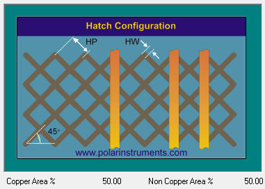
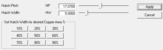
Si8000m/Si9000e XFE crosshatch configuration This approach has enabled solvers to model more closely the effects of a wide variety of crosshatch geometries. The XFE option, applicable to both Polar’s Si8000 lossless transmission line impedance solver and to the lossless mode of the Si9000 frequency dependent, lossy transmission line field solvers allows for configuration of hatch pitch (HP) and width (HW) as shown in the above graphic.
Hatch pitch and width may be specified either directly or by association with a choice of copper area settings. Set the pitch by simply dragging the Hatch Pitch slider and visually monitoring the Copper Area for the required percentage. If the desired Copper Area is known, select the %age from the preset value buttons — the hatch width will automatically be calculated for a given hatch pitch. Summary of benefits
Using Polar's XFE technique with its multiple 2-D solver passes, PCB fabricators benefit from a reduction in the number of prototype turns required to achieve the desired impedance on flex-rigid PCBs. The XFE field solver enhancement can be used to model more closely the impedance as fabricated on a flex-rigid PCB using crosshatch return planes. |
|
|
Request an evaluation |
Polarcare brochure |