|
|
|
|
|
|
Impedance – measured v calculated in woven glass reinforced laminates
Application Note AP139
|
|
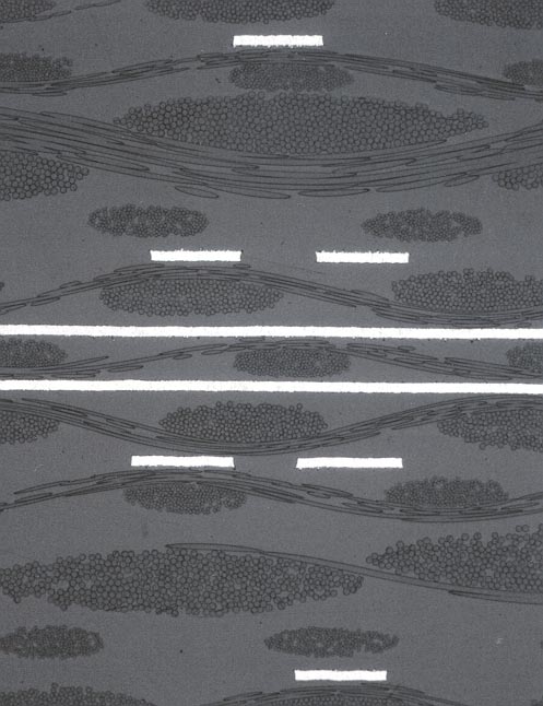
Impedance – measured v calculated in woven glass reinforced laminates How measured impedance may vary from field solver calculations when using woven glass reinforced laminates Field solvers are in widespread use for calculation and analyzing controlled impedance structures. However, when designing differential structures, especially those using fine geometries, it is necessary to have a good understanding of the base laminate and pre-preg structure in order to achieve good yields. Design Considerations FR4 (and other woven glass laminates) are composed of a curing resin system and a woven glass reinforcement. The picture below illustrates a micro-section of an FR4 pcb showing clearly two planes, a differential pair, and the bundles of glass fibers in a woven structure. The remaining space is filled with resin.
Micro section of single ended and differential traces in FR4
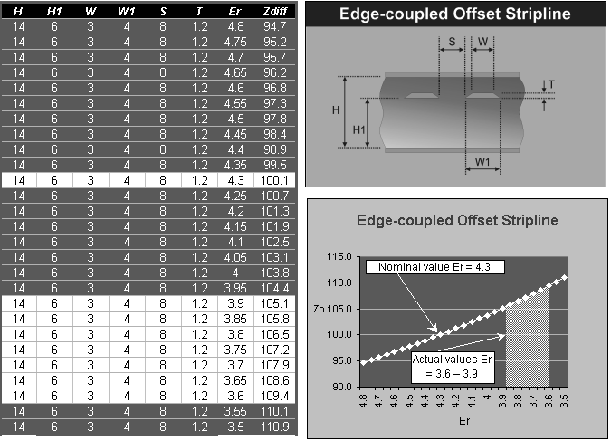
Glass has a dielectric constant of approximately 6, and the resin in FR4 has a dielectric constant of approximately 3. When differential traces are close to each other you need to take into account that the electric field "sees" a resin rich area and use a lower Er to compensate for this. Why do results differ from theory? First consider the dielectric constant, Er. Typically a value of around 4.2 is used for FR4; however, this is the nominal dielectric for bulk material. With glass having an Er of 6 and resin an Er of 3 (lower in some high performance materials) it is unlikely that the electric field experiences the dielectric constant of bulk material. Look at the differential pairs in the picture; when they are close to each other and relatively distant from the adjacent ground planes, the field is strong between the two traces. The field surrounding the pairs in the picture will experience an Er closer to that of resin than that of the glass/resin mix. If you are designing and specifying FR4 you will need to allow your fabricator more tolerance on differential traces to allow for this. If you are a fabricator, then you can achieve better yields on differential by taking into account that the effective Er will not only depend on material but also on structure and geometry. Looking at a micro-section can help you see why your results on differential traces may be higher than your design. What if my differential impedance requirements are very tight? Using a laminate where the reinforcement has an Er similar to the resin is one way of achieving this; you should discuss this with your supplier as you will need to balance the increase in yield against the increase in material costs. Laminates using a non woven aramid reinforcement offer one way of reducing the change in Er with structure geometry as the reinforcement has a value of Er similar to that of the resin. Ensure your measurements are valid Whatever TDR you use to measure impedance, please ensure that it is calibrated to a traceable impedance standard. TDR measurements need to be made with the same DC conditions at the end of the trace as those on the TDR head during verification. As most coupons are unterminated it is good practice to use reference air lines or a precision semi rigid coax which is measured against a traceable standard. Calibrating a TDR with a precision load resistance can introduce measurement errors of up to 3 or 4 ohms at 50 Ohms. Possible variations Look at the graph below. This shows you the range of impedance for a differential pair taking into account different Er; these are the types of errors you may introduce when not taking the above effects into consideration. Note that because of these effects, which are real and a result of the physical properties of the materials you are working with, when designing or tailoring your process you may need to use one value of Er for single ended traces, and another for differential configurations. You may even need a third value for coplanar structures. This may be determined experimentally by building some sample coupons and running through your process. An economic way of doing this may be to add additional coupons to boards you are already running through production. How can I make a closer prediction? Manufacturers should rely on experience as well as material specifications when choosing the Er value with which to calculate. Allow for the absence of glass between differential tracks by using a lower Er than the dielectric material manufacturer quotes for the bulk of the laminate material. Experience shows that for today's typical differential track dimensions of 5 mils with 5 – 7 mil spacing between tracks and >8 mils laminate thickness, an Er in the range of 3.6 – 3.9 for FR4 (10 – 15% reduction in Er) will achieve predictions close to actual. (See highlighted area in graph below) Using a non-woven aramid material, or another dielectric laminate whose reinforcement has an Er similar to that of the resin filler, will help overcome the problem. PCB fabricators and PCB designers should discuss the benefits of increased yield compared with increased material costs.
How a predicted Zdiff of 100 Ohms could result in an actual value of 107 Ohms Modifying designs. It is important to maintain a good dialog between the original designer of impedance controlled boards and the fabricator. To assist in this process the Polar Si8000m Field Solving Impedance Design System can goal seek new values and graph sensitivity to changes in build parameters. |