|
|
|
|
|
|
Considering odd and even mode impedance
Application Note AP157
|
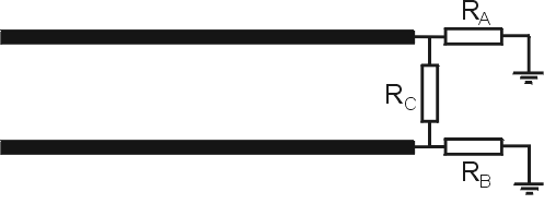
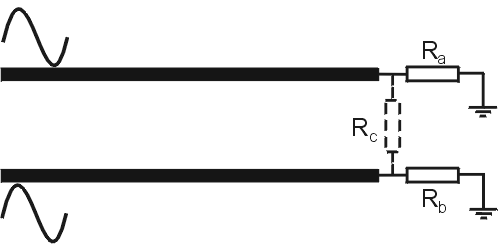
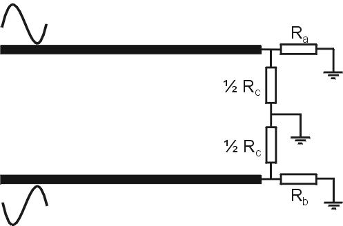
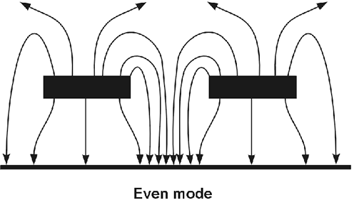
Background Coupled lines are usually designed to be driven differentially; in this case signals propagating along the line will encounter the differential impedance. This is lower than the impedance of the line on its own as the influence of the equal and opposite polarity of the two propagating signals make the structure behave as though an extra ground plane has been added vertically between the traces. Though this is an "imaginary" or "virtual" ground its influence is the same as a real copper wall. However not all signals on a pair of coupled lines will be differential; the simplest example to take is electrical noise. One reason for using differential pairs is that a low level signal can be faithfully reproduced at the receiver in a electrically noisy environment. Because the traces are close, they will suffer from identical noise exposure. Noise induced on the pair will be of both equal amplitude and polarity. So while the original signal has equal and opposite polarity and feels the influence of the virtual ground, the noise will encounter no such ground. In fact as the noise is equal on both traces, the effect is to slightly increase the impedance of both traces. The impedance seen by the noise as it propagates is therefore the even mode impedance. Definitions of impedance related terms: Single ended Zo: The impedance seen when testing a single line which is not coupled to an adjacent line Differential (Zdiff): The impedance testing between a pair of lines when driven by equal and opposite polarity signals. (Zdiff is twice the value of the odd mode impedance) Odd Mode (Zoo): the impedance seen when testing the impedance of one side of a pair of lines when the other is drive in equal and opposite polarity (half the value of the differential impedance) Common (Zcm): The impedance seen when testing into a pair of lines driven by identical (common) signals Even mode (Zoe): The impedance measured testing one of a pair of lines which are driven by identical signals (Even mode is twice the common mode value.) When is it important to consider both odd and even mode impedance? This is really a design issue and outside the normal scope of these notes; however, lets take one example — think again about noise on the signal pair considered above. Transmission lines need correct termination in order to preserve signal integrity and minimise reflections. In the case above, what is the correct termination? The signal will see the odd mode impedance, and the noise will see a higher impedance — the even mode. Should you choose the lower or higher, or a compromise value between the two? Or is there another solution? Yes, there is a third solution; it is elegant and maybe not always necessary, however it is a method of terminating both the even and odd modes. First, simply terminate the two lines with the correct even mode value of terminating resistor to ground (let's call these two resistors Ra and Rb), and then add an additional resistor Rc between the pair. Fig 1 Typical Pi termination for a coupled line pair This resistor is invisible to the even mode signals as the even mode content on each track is identical so no even mode current flows in this resistor. Fig 2b Equivalent termination (showing Rc open circuit) in even mode However, in odd mode the centre of the resistor will always be at 0v. Now this half of the resistor will appear in parallel with the even mode terminating resistor. So the odd mode impedance is equal to ½ Rc in parallel with Ra.
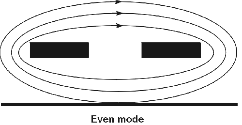
Fig 2c Equivalent termination (showing virtual ground) in odd mode This arrangement offers perfect termination to signals propagating along the line in both odd and even modes. Fig 3a Electric field in even mode
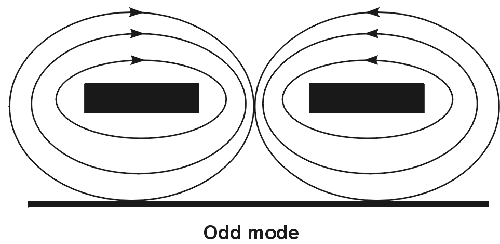
Fig 3b Electric fields in even and odd mode
Fig 4a Magnetic fields in even and odd modes
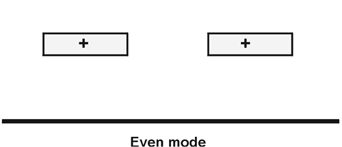
Fig 4b Magnetic fields in even and odd modes In even mode the polarities of the two propagating signals are equal.
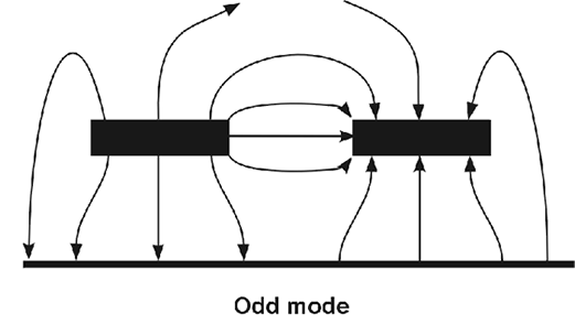
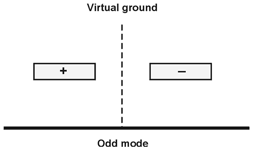
Fig 5a Even mode signal polarity In odd mode the equal and opposite polarity of the two propagating signals introduces a "virtual ground" plane between the traces.
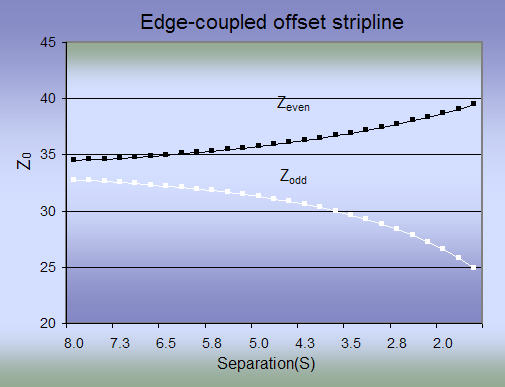
Fig 5b Virtual ground between traces in odd mode How does this effect PCB fabrication? An increasing number of designs (for example USB 2.0) call for control of both odd and even mode impedance; this means that more care needs to be taken when preparing data for impedance controlled PCBs. Now it becomes important to ensure that minor alterations to centre differential impedance values do not put the even mode out of spec, or vice versa. Polar Instruments' Si8000/Si9000 use powerful 2d field solvers to extract both odd and even mode impedance; these values may be rapidly extracted using the Si8000/Si9000 Quicksolver models, or accessed directly through the Microsoft Excel Si Interface for an in depth graphical analysis of interrelationships between structure geometry and odd and even mode (see Fig 6 below).
Fig 6 Odd and even mode impedance plotted against trace separation. More information? Further information on measuring PCB controlled impedances is available by email from martyn.gaudion@polarinstruments.com For information on field solving impedance design software please contact: ken.taylor@polarinstruments.com Further reading — if you would like a deeper understanding of some of the above, Polar recommended reading note AP194 includes a list of helpful books with more information on signal integrity issues. |