Probe force analysis of Polar GRS500
Application Note AP209
Concept of GRS500 probe operation
The solenoid driven probe head is mounted on a vertical (z axis) slide that is driven up and down by a precision stepper motor drive.
The probe is driven up or down by solenoids and if not activated is suspended by springs in mid travel.
The travel of the solenoid driven motion is 10mm and this is not adjustable: rubber cushions limit the travel and suppress noise. The probe carrier runs on a linear ball bearing and is connected to the solenoid mechanism by an optical switch assembly that allows detection of when the probe is touching the PCB under test.
During testing the actual compression to which the pin is subjected is set by the position of the z axis slide. While testing, only the solenoid is used to retract the probe when moving around a component (e.g. an integrated circuit) but for across the board moves the Z-mechanism is also employed to increase the clearance or fly height.
The replaceable probe pin consists of a shell containing a spring and a test pin or needle. The spring is preloaded so the needle does not move until the applied force reaches a certain level. Pressure increases with travel up to maximum compression. The graph below shows the characteristic of the pin tested.
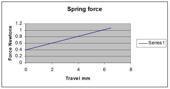
In normal operation the pin is compressed by about 2mm which allows a reasonable variation in solder height between test samples while maintaining a firm contact pressure of about 0.6 Newtons (60 grms wt. or 2.11 ounces
wt.)
Analysis of forces
The probe pressure on the board during testing is a combination of two
effects:
the pressure due to the spring in the test
pin,
the momentum of the moving needle as it strikes the board.
To assess this the velocity of the probe is first measured at the height at which the board would normally
be mounted. This was measured at 1.5m/s.
The weight of the needle was measured with a microgram balance at 78mg. The impact energy
(½mv2) = 87.75 micro joules This is approximately the same as dropping the needle from a height of 100 mm.
NOTE: This calculation refers to the needle and not the whole needle/spring/shell assembly which is the replaceable test pin. The forces in the moving probe carrier and solenoid assembly are absorbed by the rubber cushions and are NOT transmitted to the needle which slides
within its shell and is supported by the spring.
The effect of the forces applied to the pin on the board under test will to a large extent depend on the characteristics of the surface being probed.
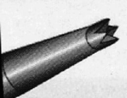
The recommended pin (supplied by Polar - part No PRB100) has a crown style tip of diameter 0.28 mm.
The sharp points of the crown are intended to puncture surface oxide and flux on the test pad and can in some cases cope with thin conformal coatings. Some penetration of the crown points into the metal is desirable to break up surface films and as this occurs will absorb the kinetic energy of the tip. However it is the spring pressure which is dominant (a force about 100 times the weight of the pin) and will cause the majority of surface effects.
Note that the mass of the solenoid driver and the probe carrier have no effect on the probe tip as this is freely suspended in the probe shell and only connected to them by the spring. Noise generated during operation is due to the solenoids
not the probe contacting the board.
On critical (usually gold) surfaces test pins with a smooth radiused tip can be used, but will only be reliable if the contact material is completely clean.
Conclusion
The marking of the surface is an inevitable consequence of the probe design which is intended to break surface films to achieve reliable contact with the board being tested. The forces applied are controlled and in no way related to the moving mass of the probe carrier assembly.
The impact of the probe needle on the board is approximately equivalent to dropping the needle from 100mm.