PCB test - locate faulty digital ICs easily with In Circuit Functional Test
Polar Home
Printer Friendly Version
Application Note 111

PCB test — locate faulty digital ICs easily with In Circuit Functional Test


Printer Friendly Version
Sophisticated software device simulation techniques in modern ICT Fault Locators now allow rapid and effective location of faulty digital ICs without removal from circuit.

What is ICT?
In-Circuit Functional Test (ICFT or ICT) is an easy to use but highly effective method of locating faulty digital devices. ICT provides accurate software simulation of a device's behaviour in its circuit configuration allowing the trouble-shooter to perform a functional test of a digital device while the device is still in circuit or wired on a PCB. ICT enjoys a high success rate with a wide variety of digital ICs. For example, using ICT you can easily check that a simple logic gate operates in accordance with its truth table or that a counter or shift register correctly responds to a known number of clocks. ICT is especially effective in locating faults in the "glue" or interconnecting logic of micro-processor circuits ; it's not restricted to simple logic elements however — you can check that programmable devices such as ROMs or EPROMs have been properly programmed or that programmable interface devices respond correctly to control words.

The ICT Fault Locator
The ICT fault locator compares the logical function of the device under test with the corresponding "ideal" device in the fault locator device library, a database of device "models". Each device model in the library includes a sequence of test patterns that will initialise the device, drive the input pins of the device and check for appropriate responses on the device output pins. During testing, the logical operation of the device (i.e. the relationship between inputs, clocks, control signals and outputs) is displayed by the fault locator in diagrammatic form and compared with the "ideal" device in the database.

Building a reference device
When testing a device in free air you can usually simply locate a test clip over the device, specify its type and test the device. The device is compared against its library model. For devices in circuit the fault locator can use auto-compensation to build a software model of the device from its circuit configuration. The way a device is connected in circuit controls the logical function of the device. Suppose you are testing a binary counter such as a 74161. The counter outputs can be connected to the inputs to produce a counter with a different base (e.g. divide-by-five, etc.). The fault locator tests for connected pins (links) then builds a software model of the counter in its connected configuration. The software model then serves as a reference device - a model of how a good device behaves in a good circuit. If a reference board is available you can use the fault locator to acquire reference signatures - i.e. how the 74161 operates in a good circuit in order to create a reference device. During the reference acquisition process the fault locator will record the behaviour of the counter in a good circuit and note the differences from the standard counter state table - the differences are recorded and become part of the reference device model. This model is then used during the test process as a reference when testing suspect boards Test results will typically be shown as simultaneous reference and device-under-test displays of links and logic diagrams, allowing easy identification of faulty devices.


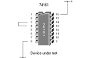
Short detected between pins 3 and 4
The Links diagram
Many faults are due to wrong connections between IC pins, open or short links, pins stuck high or low, etc. The fault locator displays shorts and opens in the links diagram.

In the example to the left, the fault locator has detected an unexpected link (i.e. a short) between pins 3 and 4 of the IC.


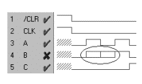
The result of the short between pins 3 and 4
The Logic diagram
Detail from the resulting logic waveform diagram is shown below. Reference and DUT waveforms are shown in different colors for easy identification - in this case the ringed area shows the effect of the short on the device behavior. The short would now be rapidly pin-pointed.
ICT's unique ability to simulate device in-circuit behavior and its graphical display of logic problems provide a powerful tool for rapid trouble-shooting down to component level. If you have a trouble-shooting technique you would like to share with other Polar fault locator users please fax or email Polar Instruments on the number below.

Polar Instruments Ltd

polarinstruments.com
mail@polarinstruments.com

Tel: +44 1481 253081 Fax: +44 1481 252476 © Polar Instruments 2002


© Polar Instruments 2002. Polar Instruments pursues a policy of continuous improvement. The specifications in this document may therefore be changed without notice. All trademarks recognised.