PCB
test — Power to
Ground shorts
How the Toneohm 950 helps you find them,
and, how FTCam Pro can give you further help with plane
short location on complex boards
|
||
| Printer Friendly Version | |
|
Application
Note 201 PCB
test — Power to
Ground shorts |
|
|
|
| Printer Friendly Version | |
| Background Have you ever scrapped a board (loaded or bare) because of an internal power to ground short? Expensive isn't it? This note explains how the Toneohm 950 works to help you repair many of those boards you may have considered a write off. Secrets of VPS
"Vector Plane Stimulus" |
VPS connections to a plane |
|
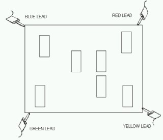
How does VPS find plane to plane shorts?
Using a 950 you connect 4 Plane stimulus leads (VPS) to the 4 corners of the ground plane, a further lead is connected to reference the other side of the short, (whether another plane or a track). The magic of VPS happens on the plane driven by the 4 stimulus leads. First current is passed from the top left corner of the plane to the bottom right corner, lets call this phase I, second current is passed from the top right corner to the bottom left (phase 2) Current passes diagonally across the board in each of the two phases. Lets think about what's happening in phase I, imagine for a while the plane is not a plane but a rectangular conductor, shrink this in your mind until it is thin — very thin, in fact just a piece of wire. Now in phase I the VPS current flows from left to right along the wire. Again imagine one point on the wire (the imaginary shrunk plane) where it is shorted to an adjacent plane. Visualise connecting this point to the –Ve lead of a high impedance Voltmeter. Connect now
the +Ve lead of your imaginary voltmeter to a range of points on the wire,
Move left and the further you go the Higher the positive voltage reading.
Move right and the more –Ve, at the point where the leads are together you
will see 0v. On a faulty board the Ov reading is on an equipotential line,
the location of the short is at one point on this line. |
How
can FTCam help?
By reading your cad data
into FTCam you can display the copper areas of the ground planes. Treat
each plane as if it is a separate PCB. When you look at the data using FTCam you can clearly see the extents of the copper on inner layers. Use this graphical information to help you connect the Plane short stimulus (VPS) leads correctly.
Toneohm
short direction |
| Pointing
in the right direction VPS not only looks at the magnitude of V1 and V2, it also monitors the polarity and uses this information to display a directional arrow on the front panel of the Toneohm 950, this in conjunction with a tone that rises as you approach the short lets you localise the fault into a small area. You may find on very dense boards or boards with BGA it helps to X-ray in the locality identified by the 950. |
|
| You can find a more detailed graphical description of VPS in AP202 which is a PowerPoint presentation. AP202 gives step by step information on the operation and underlying technique of VPS | |
| More
information? Further information on PCB faultfinding please email: mail@polarinstruments.com If you are reading this in the UK: For information on PCB faultfinding please ask: neil.chamberlain@polarinstruments.com |
|
|
|
|
Polar Instruments Ltd polarinstruments.com Tel: +44 1481 253081 Fax: +44 1481 252476 © Polar Instruments 2002 |
 |
|
|
|
| © Polar Instruments 2002. Polar Instruments pursues a policy of continuous improvement. The specifications in this document may therefore be changed without notice. All trademarks recognised. | |