PCB test test list operation on GRS500
| Home | |
| Printer Friendly Version | |
|
Application Note
204 PCB test test list operation on GRS500 |
| Printer Friendly Version | |
| This
application note supplements the GRS500 operator manual. If you need an
overview of the GRS500 please refer first to application note AP203 |
|
|
|
|
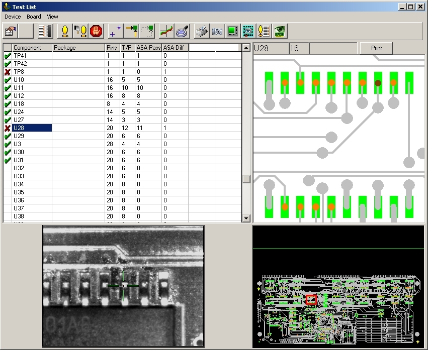
| The Test List mode of the GRS500 allows you to save and compare nodal impedance of a known good board against that of a board that is undergoing troubleshooting. | |
| Important safety note: Before using the system please read the operator safety guidelines in the user manual, and familiarise yourself with the basic operation sequence described in this note. Importing data from CAD and CAM systems is dealt with in specific notes which refer to each individual CAD system supported. | |
| This application note provides you with a guide to the test list icons in the GRS, it is well worth investing a few moments familiarising yourself with this document, 10 minutes spent reading this will save you valuable hours when you first use the system. | |
|
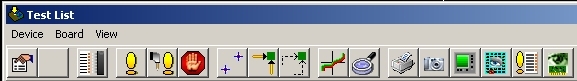
Example test list |
|
|
Set test properties: For setting ranges, comparison tolerance and common channels. |
|
Align: Pressing this icon allows you to align the board under test to the presently loaded test position data. |
|
Component pins list: Displays component pin and net information for the selected test entry |
|
Test selected device(s): Initiates the GRS500 to probe the allocated test points on the highlighted devices in the list. |
|
Test all: The GRS500 moves to probe all allocated test points on the test list. |
|
STOP: Stops testing |
|
Test view: See the nodal impedance comparison data. |
|
Inspection mode: Fly the view camera directly over the device pin under test. |
|
Toggle Camera: Turns the live video display on and off |
|
Live instrument: Allows you to position over a suspect device, probe, and display the nodal impedance in real time. |
|
Videosectioning: With videosectioning selected you can compare a stored image of the board under test with live video from the GRS500 camera system |
|
Board view: This returns you to the default view of the board data. |
|
What do I do next? Once comparison test is complete, you simply return to board view and select troubleshooting mode to enable you to analyse nets which show differences |
|
Polar Instruments Ltd www.polarinstruments.com Tel:
+44 (0) 1481 253081 |
 |
| © Polar Instruments. Polar Instruments pursues a policy of continuous improvement. The specifications in this document may therefore be changed without notice. All trademarks recognised. | |