Application note 208
Using
the External Instruments function on the GRS500

The GRS500 External Instrument function allows the GRS500 user to link the GRS500 to external test/measurement equipment. The operator typically would use the facility to make test or troubleshooting measurements in addition to the signatures provided by the GRS500; for example measurements could include resistance or voltage tests or a low frequency signal displayed on an oscilloscope.
Note: The Switchable Commons card (part number MSA256) will be required for external instrument operation. Ensure the card is fitted prior to selecting External Instrument operation
Ensure that the GRS500 hardware and measurement system will support the extra channels required for external control. Select the GRS500 rear panel socket configuration from the Config|External Instruments screen (shown below refer to the socket layout on the rear panel).
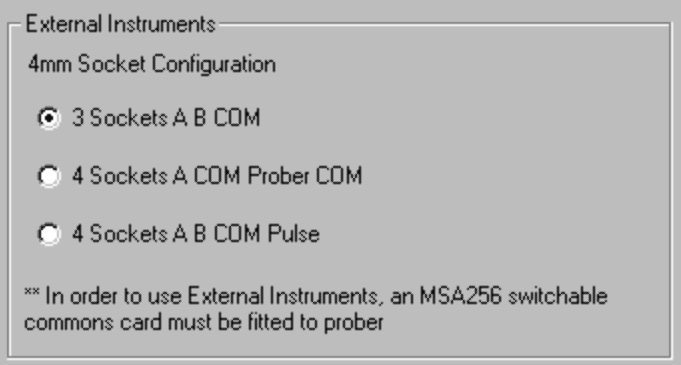
Note: Only the 4 socket choices allow the use of the External Instruments option. By default the 3 socket option is selected, (disabling the External Instruments option).
Specifying the External Instrument operation option enables the External Instrument button on the main toolbar. Clicking the External Instrument button switches control from the GRS500 software to an external program.
Connection for external instrument
Connection for external instrument is by two 4mm sockets.
Maximum voltage is 40VDC
Frequencies above 1MHz are not recommended as the probe has no provision
for a ground connection.
There is no possibility of using an oscilloscope probe or any device other than
the standard GRS probe .
Auxiliary power to the device under test.
A 25 way cable runs from the table to the back panel. This may be used to take signals or power to the device under test. No switching is provided so the user must arrange to remove all power and signals when making ASA measurements. Current rating is 300mA per pin, 40V max.
GRS500 External Instruments Programming Interface
Note: The information given here assumes the programmer is familiar with Visual Studio v6 and the use of objects.
The GRS500 External Instruments Programming Interface allows the GRS500 user to write a small program to allow the prober to go to any pin/testpoint in the currently running GRS500 program. The Programming Interface also provides control of the switchable COM set-up. This user created program would normally run after the GRS500 tests had run. Programming information is shown below.
The GRS500 object has one class called ExternalInstruments
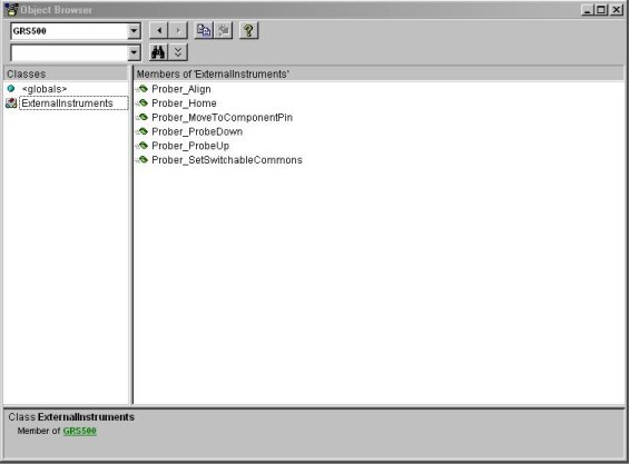
The Class has six members
Prober_Align
Display Prober Alignment dialog
Prober_Home
Homes Prober
Prober_MoveToComponentPin
Requests prober to move to specified pin on loaded GRS database
Boolean=GRS500.Prober_MoveToComponentPin(strComponent, strPin)
If Boolean equals False then strComponent, strPin were not found
Prober_ProbeDown
Probe down at current location
Prober_ProbeUp
Probe up
Prober_SetSwitchableCommons
Requests prober to switch Commons.
GRS500.Prober_SetSwitchableCommons(intSwitchableCommonsValue)
Where intSwitchableCommonsValue equals one of the following values :
Prober Common 1 = 8
Prober Common 2 = 4
Prober Common 3 = 2
Prober Common 4 = 1
Prober All Commons = 15A sample External Instruments test application (including source code) is available in the GRS500 installation folder
